
Study: TwoFour54 Workflow
ADMZ 1 is essentially composed of three city blocks: Blocks E, H and L, with additional set storage facilities located on Block D. The three story podium of blocks E and H houses the broadcast studios, retail and the common areas related to hotel and serviced apartments, as well as residential units. The podium of block L features a training academy, exhibition areas, incubator facilities, a media club and the TwoFour54 offices.
Below these three blocks is a two-story underground car park, from which each of the blocks can be accessed through the 'Connector'. The 'Connector' is an internal pedestrian galleria within blocks E and H, which widens where the vertical circulation elements are located to form internal public plazas at ground level. In block L, the 'Magnet', a centrally located atrium, incorporates the circulation to the different components of this block and creates a public plaza right at the core of the media programme.
Above the podium levels of each block, two towers are located diagonally in an east-west direction. At block E the southern tower contains the hotel and serviced apartment programme, whereas all other towers are considered for office use. Access to the cores and main lobbies of these towers is located at ground level along the 'Connector'.
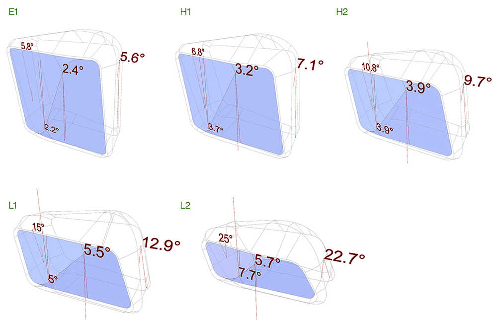
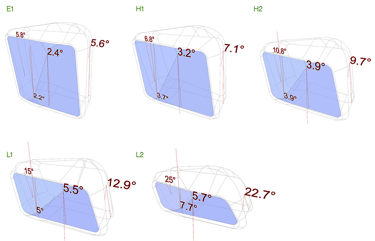
Five of the six towers that lay on top of the three podium blocks have the same geometry principle. The towers have a symmetrical geometry composed by two main groups, frame and facade. The central spine of the frame has four surfaces, top, bottom and two sides, connected by curved surfaces at the corner junctions.
The surfaces of the central spine have different inclination accordingly with the design and the programme requirements. The connection of the central spine of the tower with the facade part is made by the tapered extension of the central frame.
The towers have an east-west orientation that, in conjunction with the enclosed frame concept for those exposed facades, brings many advantages to the energy consumption of the buildings. The facade’s geometry is defined by a diagonal line that divides the glass facade in two pieces. The inclination of the central line is defined by the facade modules that will be applied to the tower. The two facade pieces rotate along the diagonal cut which has a constant distance along the z axis. The glass rotation is one of the main factors that define the characteristic shape of the building. The south facade is a double skin facade that works as an external shading device with three levels of shading – the outer fitted layer of glass, the horizontal walkways and the diagonal glass fins. With a 25% frit on the external layer and high transparent inner layer, the double skin facade while allowing for a better quality of natural light with the working places also significantly reduces the heat radiation from the facade increasing the comfort for the users.
The north facade is a single skin facade due to its lesser exposure to the sun but follows a similar geometrical articulation with the diagonal fold. The apparent simplicity of the design is achieved by a complex series of geometrical relations between several technical and architectural dimensions that include the angles of the transfer structure, the minimum lease depth of the office spaces, the height of the lift overruns and the building maintenance unit range and house. Resulting from these requirements and from set of parameters of folds, tangencies, diagonals, height allowances, the towers acquire very different characters depending on their number of floors, length and depth. The hotel tower frame stems from a similar set of parameters. However, its facade is radically simpler.
The decision of develop a parametric model was made because of the necessity of an instrument that would have allowed us to manipulate the towers geometry and stay in control of our design, addressing all of the issues that we eventually were going to face during the concept design, schematic design and design development.
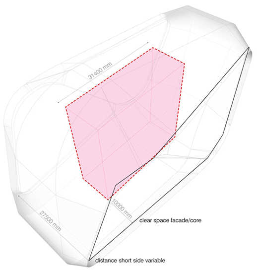
The very fast achievement of a workable parametric model right after the competition phase gave us the opportunity of test several configurations in a very short time, even though the surfaces generate from the model presented double curves and the design wasn’t quite what we were seeking, that model allowed us to perform several test such as gross floor area calculation with different configuration of floor numbers, inclination and width based on the minimum distance required form the core to the facade.
The typology of the project, five towers with the same main geometry, made very successful and indispensable our parametric model due the deadlines schedule and the very fast reaction to the consultant comments and issues that we had to provide.
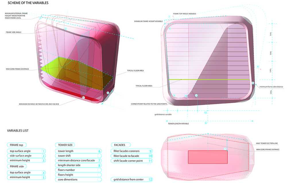
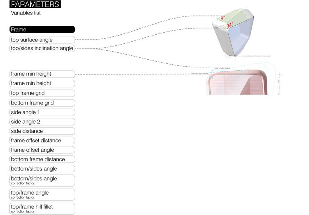
The parametric model has been developed in parallel with the design phases adding elements that gave us more control and more flexibility in terms of proportion and key control elements and data output. The first model had just few variables that allowed us to roughly modify the tower height through floors number and height, tower width, core dimension, grid size inclination in a very simple way.
The chain reactions that take place every time there is a parameter modified, in order to be able to have the full control and flexibility of the tower necessitated to introduce many control elements such as sides angle control, frame offset distance, lower frame plane angle, frame angles fillet, minimum clear space facade core, distance short side, tower length, facade kink grid inclination, facade kink stuck joint level, double facade offset, facades curves control.
One of the main advantages we had using the parametric model has been the integration with the structure.
The structure is vertical columns on the central part of the tower and four inclined columns that follow the tower inclination with a transfer structure on the lower part of the tower (hill) that transfer the loads to two mega columns into the podium.
Without having any real 3D model or nurbs surfaces open in Rhinoceros we could open the structure that we got from the engineers and through Grasshopper modify the variables and change the tower proportion in real time, make screenshots and send the comments back for a revision of the structure if necessary.
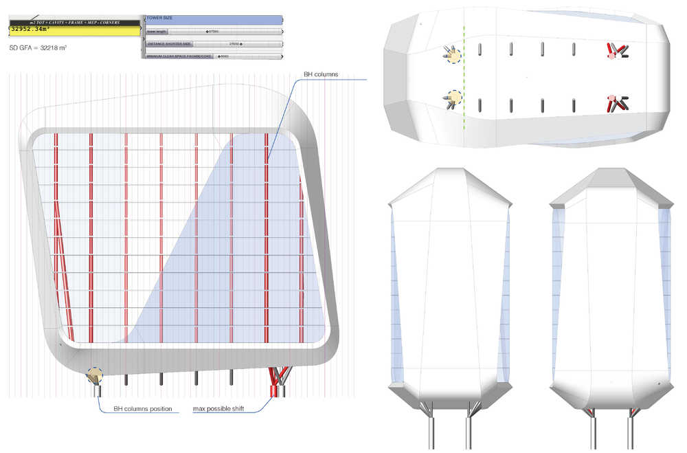
The variables involved in this exercise were the side frame variables: angle one and two and side distance that effect the tapering on the side surfaces and as consequence the lower hill and the top hill. The lower and top hills variables: lower frame distance, lower frame angle adjust, lower frame side plan, frame top sides inclination angle, frame top side angle, frame min height. Other parameters like tower length, distance shorter side, minimum clear space facade/core, also change the geometry of the tower but they increase considerably the GFA of the building.
The parameters that control the tower inclination are very important because responsible of one of the esthetical scope of the project which is the elegance and dynamism of the ensemble achieved by the different proportion, orientations and inclinations of every single tower.
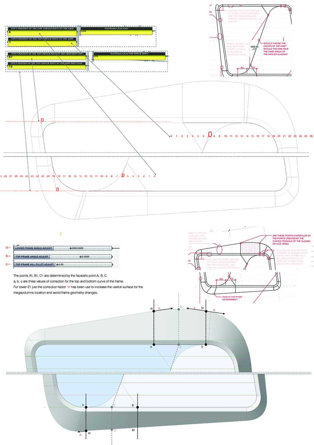
From a first simple definition of the angle based on a grid, in accordance with the structural grid, centered with the core position, successively we have introduces two grids, one for the top part of the tower and one for the bottom, in this way we could manage the inclination and the core position independently and have more control of the tower location on the podium.
The inclination of the facade kink is defined by two grids independently editable in order to be able to keep the inclination wanted and move it along the the x-axis to increase or decrease the distance between top and bottom rounded corner to the facade fillet.
To generate the plans for every floor of every tower we use two different scripts: The first is a Rhinoscript (Level manager toolbar) that cut the towers in according to a spreadsheet that lists four levels of section, F2F, SSL, FFh+x, FFH+x, exporting automatically DWG files by level number and program category. The categories are selectable at the beginning of the script, -geom, -stru,-faca,-gfa.
The second step is a vbascript for AutoCAD that opens the files saved and clean up lines and based on the file typology adding hatches at the sections and hatches for area calculation with attribute block already placed.
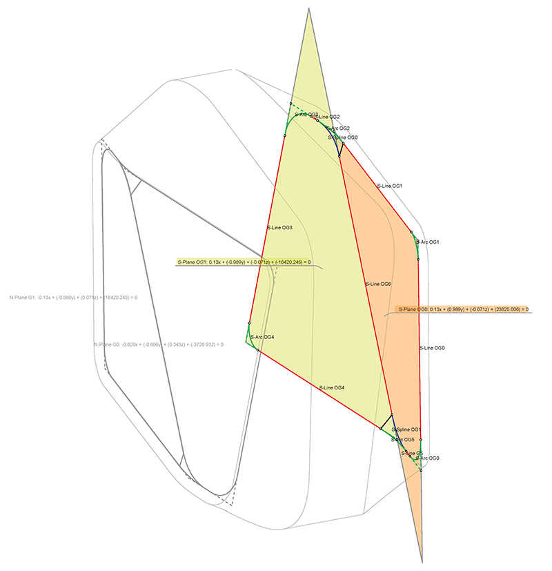
The expressive geometry of the towers is controlled by an exhaustive list of input parameters and output data. The length and breadth of the towers at the short ends and the 'big frame' is constrained by the typical set-outs from the core. In a detailed view of frame and glass facade geometry one can see the breakdown of the geometry into simple planes, lines and minimal splines.
UNStudio Team: Ben van Berkel, Astrid Piber with Nuno Almeida and Albert Gnodde, Andreas Bogenschütz, Ariane Stracke, Chiara Marchionni, Jeong Eun Choi, Florian Licht, Ger Gijzen, Gustav Fagerström, Iris Pastor, Jaap Baselmans, Jaap-Willem Kleijwegt, Jay Williams, Ka Shin Liu, Kristin Sandner, Margherita Del Grosso, Martin Zangerl, Mirko Bergmann, Patrick Noome, René Rijkers, Rob Henderson, Silvia Filucchi, Stefano Rocchetti, Thomas van Bekhoven